Chapter 1 - Collection of Data on Outgas of Organic Materials for Space Use

1. Introduction

2. Outgas Measuring System

3. Overview of Outgas Measurement

4. Comparison with Data Collected by Other Organizations

5. Data Application

6. Photos on Measurement of Outgas


1. Introduction

In 1978 and 1979, the National Space Development Agency of Japan (NASDA) developed an outgas measuring system in Japan for outgas of organic materials for space application using as an example a test method under ASTM E 595 (Standard Test Method for Total Mass Loss and Collected Volatile Condensable Materials from Outgassing in a Vacuum Environment) recommended by NASA. NASDA installed the system in the Calibration and Standard Building in its Tsukuba Space Center and established a standard measurement method in 1981 after making efforts for this purpose in 1980 using this system. In 1981, the system was moved to the outgas measurement room in the Electronic Equipment Test Building, which was completed in that year. A high-precision micro electronic force balance was installed for measurement of sample weights and full-scale measurement of outgas was started.
As the system aged, in 1994, the outgas system was replaced with a new system and in 1997, the micro electronic force balance was replaced. This collection of outgas data summarizes measurement data after September 1980, the first edition of which was issued on March 25, 1991. Since then, additional data has been distributed as notices. Changes made in the specifications and procedures as a result of system upgrading and reflection of the large volume of stored data on the database necessitated rewriting of chapters 1 and 2 as a whole. The 1999 version of the data collection is distributed as Revision A.
It is hoped that this collection of outgas data will continuously be used in various fields including space development. NASDA is making public its "Material Database System" including outgas data, in its homepage, which contains useful information.

2. Outgas Measuring System

The outgas measuring system installed at NASDA in 1994 and owned by NASDA is outlined below. (Data as of April 22 1999)
Equipment Performance/Function Remarks

A. Outgas Measuring System
  (ASTM E595-93 compliant)
  
NOTE: The system was replaced in 1994 and has been in operation since 1995 to collect data.


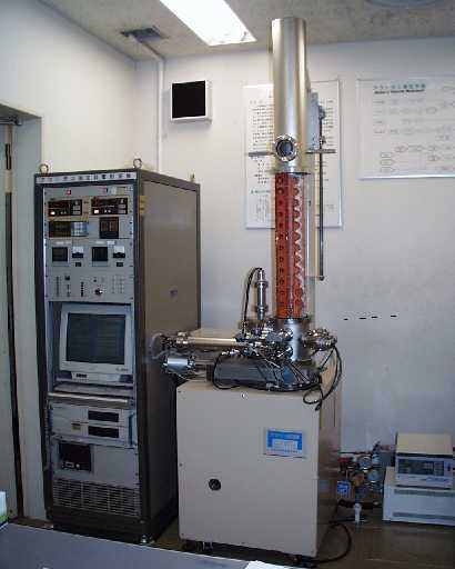
1. Vacuum Evacuation System

1.1 Vacuum Level
        8 × 10 -4 Pa or less

1.2 Vacuum Pump
(1) Oil rotary pump
      Throughput 330L/min
(2) Turbo-molecular pump
      Throughput 500L/sec

1.3 Vacuum Gauge
(1) Pirani gage
(2) Ionization vacuum gage

1.4 Vacuum Chamber
        140mm diameter × 700mm height

1.5 Operation
        Automatic operation by computer
 

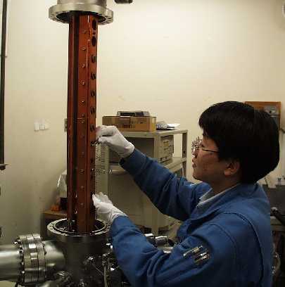
2. Sample Measuring System

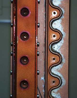
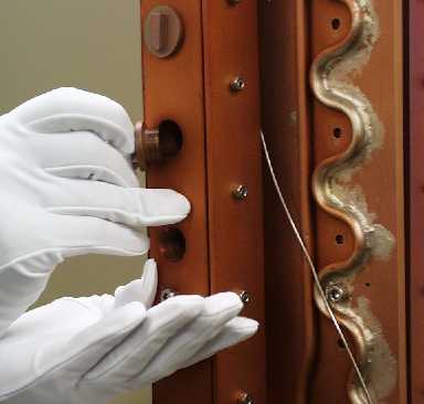
2.1 Sample Measuring Chambers
        For normal measurement (diam. 26mm): 15 chambers
        For standard samples (diam. 26mm): 3 chambers
        For large samples (diam. 40mm): 3 chambers
        For film thickness measurement (diam. 26mm): 1 chamber
        For IR measurement (diam. 26mm): 2 chambers

2.2 Concurrent Tests
        Five tests can be undertaken simultaneously

2.3 Heating Rod
        Normally heated to 125°C.

2.4 Cooling for Condensation
        Normally 25°C.


2.5 Film Thickness Gage (Quartz crystal oscillation)
        Indication range: 0 to 9999nm

2.6 Quadrupole Mass Spectrometer
        Model: MSQ-400
        Mass range: 1 - 400


No load, no heating
and no samples


Number of samples in ASTM E595 tests is 3. Five tests can be conducted simultaneously if all 15 sample chambers are used.


B. Weighing System

NOTE: This system was replaced in 1997 and has been in operation since 1998 to collect data.

1. Micro electronic balance
    Model: MT-5 (METTLER)
    Minimum indication: 1 × 10 -6g
    Maximum value: 5100mg


C. Analysis of Collected Volatile Condensable Materials


1. Infrared spectrophotometer
(1) Model up to March 1999: A-302 (Mfd. by Japan Spectroscopic Co.)
    Range: 5040 - 330cm-1
(2) Model since April 1999 Supectrum One (Mfd. by Perkin Elmer)
    Range: 7800 - 350cm-1


D. Others


1. Ultrasonic cleaner for equipment cleaning
 

2. Vacuum dryer (Can heat up to 150°C)
    For drying cleaned parts and desiccants
 

3. Desiccator
    For sample storage


3. Overview of Outgas Measurement

Outgas measurement by NASDA is outlined below.

3.1 Overview of Test

(1) Measured samples

Materials for outgassing measurement are mainly organic materials. Normally, samples are cut into shapes of rectangular parallelepiped with side lengths of 1.5 to 3.0mm. However, inorganic materials such as ceramics that cannot be cut or machined easily, small electronic components and other materials and parts can be measured in non-standard tests.
See chapter 3 Reference Data (V) "Preparations of Outgas Measurement Samples" for adjustment of samples for measurement.

(2) Measurement items

Three items are measured as outgas data; Total mass loss (TML), collected volatile condensable material (CVCM) and water vapor regained (WVR). All these items are acquired by calculating ratios of mass before and after exposure to test environment in percentage. Average values of three samples tested at the same time are used as measurement results.

(3) Test environment

Samples are exposed to the following test environment:

3.2 Overview of Outgas Measuring Procedures

The outgas measuring procedures are specified in the NASDA Document GDM-97003 "Outgas Measurement Procedures," which are outlined below.

(1) Sample preparation

a. Samples are cut to rectangular parallelepiped with side lengths of 1 to 3mm.
b. Three aluminum boats are formed per sample.
c. Aluminum boats, collector plates and parts of the measuring system are ultrasonic-cleaned.
d. The aluminum boats and collector plates are put in a desiccator for storage.

(2) Preparing measuring system

a. The bell jar of the outgas measuring system is opened and the heating rod, cooling plate and other parts are cleaned with a washing solution.
b. The bell jar is sealed and is evacuated for four hours at 7 × 10⁻³Pa or less and 150°C.

(3) Measurement 1

a. Aluminum boats are weighed using a micro electronic force balance.
b. Samples 200 to 300mg each are put in weighed aluminum boats. (Three boats per sample)
c. The samples put in aluminum boats are stored 24 hours at 23±1°C and 50±5% RH.
d. In 24 hours, samples are weighed initially by a micro electronic balance.
e. Next, the initial weights of the collector plates are weighed.

(4) Measurement 2

a. After completing Measurement 1, the bell jar of the outgas measuring system is opened and the collector plates are mounted on the cooling plate.
b. A KBr cell is mounted when measuring infrared spectroscopic characteristics of a condensate. A film pressure sensor is mounted when measuring deposition condition of a condensate.
c. A material is inserted in the sample chamber of the heating rod, a screw lid is mounted and the bell jar is sealed.
d. The outgas measuring system is operated for 24 hours at a degree of vacuum of 7 × 10⁻³Pa or less, heating temperature of 125±1°C and cooling plate temperature of 25±1°C.
e. After operating the system 24 hours, evacuation and heating are stopped, a dry nitrogen gas is introduced into the bell jar and the heating rod is cooled below 50°C.
f. The bell jar of the outgas measuring system is opened and the samples, collector plates, KBr cell and film pressure sensor are dismounted. The KBr cell is evaluated for spectroscopic analysis by an infrared spectrophotometer.
g. The dismounted samples and collector plates are weighed by a micro electronic force balance after they are tested and total mass loss (TML) and collected volatile condensable material (CVCM) are calculated.
h. The bell jar is sealed and the inside of the outgas measuring system is maintained evacuated.
i. After measurement, the samples are kept 24 hours at 23±1°C and 50±5% in relative humidity.

(5) Measurement 3

In 24 hours, the samples after moisture absorption are weighed on a micro electronic balance and water vapor regained (WVR) is calculated.

(6) Preparation of report

The following items are calculated based on the collected data and an outgas measurement report is prepared.
a. Total mass loss (TML) (%)
[(Sample weight before test - Sample weight after test)/Sample weight before test] × 100
b. Collected volatile condensable material (CVCM) (%)
[(Collector plate weight after test - Collector plate weight before test)/Sample weight before test] × 100
c. Water vapor regained (WVR) (%)
[(Sample weight after moisture absorption - Sample weight after test)/Sample weight before test] × 100

4. Comparison with Data Collected by Other Organizations

Data collected by the outgas measuring system of NASDA and data collected by other organizations is compared as follows.

(1) Measuring system operated 1981 - 1994

In cooperation with the NASDA Safety and Reliability Department, in January 1981, a comparison test was conducted with the NASA Goddard Space Flight Center. Samples of five materials obtained by NASDA were sent to NASA and both organizations obtained measurement results as shown below.
The comparison test showed that the data obtained by the two organizations was almost on the same level.
   TML(%) CVCM(%) WVR(%)
Material
NASA
NASDA
NASA
NASDA
NASA
NASDA

Mylar

0.25

0.24

0.00

0.00

0.20

0.15

Kevlar 29

2.18

2.02

0.02

0.27

1.77

1.55

Teflon

0.01

0.02

0.00

0.00

0.00

0.04

Epoxy

1.07

1.20

0.01

0.04

0.30

0.17

Silicone SH1840

1.57

1.74 - 1.90

0.71

0.66 - 0.82

0.01

0.00 - 0.05
NOTE: In 1981, NASDA was using silicone SH1840 as standard samples and had a large number of data groups. The NASDA data for silicone SH1840 represents groups of data in ranges xxx to xxx.

(2) Measuring system replaced in 1994

NASDA joined the global round robin project of outgas measuring systems (ASTM E-595 compliant) undertaken by the American Society for Testing and Materials (ASTM) between September 1997 and January 1998. As of January 1999, ASTM was aggregating and evaluating the project results and results of interim aggregation are shown below. The results show that the data obtained by NASDA is on the same levels as those of other foreign organizations.
  
TML(%)
CVCM(%)
WVR(%)
Material
NASDA
Overall
average  
Overall
STD DEV.
NASDA  
Overall
average  
Overall
STD DEV.
NASDA
Overall
average  
Overall
STD DEV.

RT-555SHRINK
TUBING

0.208
  

0.236
  

0.034
  

0.003
  

0.023
  

0.018
  

0.042
  

0.057
  

0.020  
  
RSE13329 Silicone Wire
Insulation

1.039
  

1.135
  

0.232
  

0.275
  

0.275
  

0.123
  

0.016
  

0.064
  

0.082
  

CV-1142 Silicone

0.388
  

0.404
  

0.052
  

0.017
  

0.032
  

0.030
  

0.040
  

0.081
  

0.3314
  

CV2500
Silicone Nusil

0.149
  

0.145
  

0.028
  

0.007
  

0.007
  

0.009
  

0.003
  

0.013
  

0.016
  

5. Data Application

When using data, TML of 1.0% or less and CVCM of 0.1% or less, which are the values recommended by NASA, can be regarded as criteria for material selection. Nevertheless, amounts of outgas generated greatly vary depending on material consumption, use environment and other factors. For this reason, materials must be selected after studying impacts of outgas for the entire system notwithstanding the values recommended by NASA, especially with materials that are used in large quantities and with those that are used near an optics system which is sensitive to contamination by outgas.

6. Photos on Measurement of Outgas

Photo 1 External View of Outgas Measuring System

External View of Outgas Measuring System

Photo 2 Mounting of samples on heating rod

Mounting of samples on heating rod

Photo 3 Heating Rod and Cooling Plate

The apparatus on the left shows the heating rod. Samples are inserted through holes and lids are placed on the holes. The backside of the cooling plate is shown on the right. Screw holes for mounting the collector plates and copper tube for cooling water are visible.
Heating Rod and Cooling Plate

Photo 4 A lid is placed on a sample hole.

Outgas is released through the opposite side. The collector plates to deposit a recondensate will be mounted near the holes through which outgas is released.
A lid is placed on a sample hole.

Photo 5 Micro Electronic Balance

Micro Electronic Force Balance

Photo 6 FT-IR (Infrared Spectrophotometer Model)

Infrared Spectrophotometer Model FT-IR

Photo 7 Samples for Measurement

After TML measurement, samples are stored 24 hours in this condition for WVR measurement.
Samples for Measurement

Photo 8 Collector Plates

Recondensate is deposited on some of the collector plates.
Collector Plates

Photo 9 Outgas weighing

  Outgas weighing

Photo 10 Collector plate deposited with recondensate

Collector plate deposited with recondensate